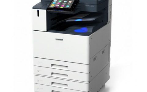
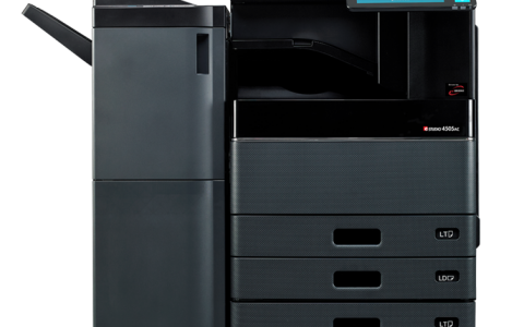
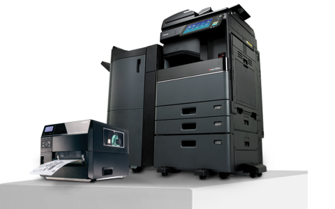
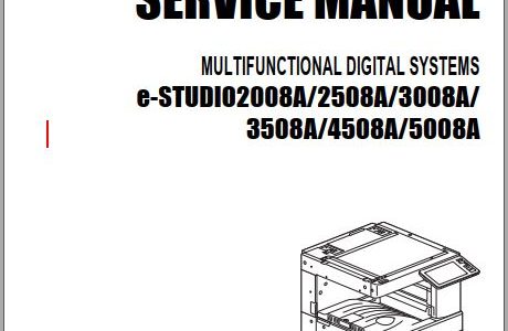
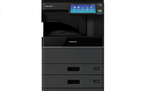
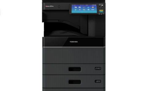
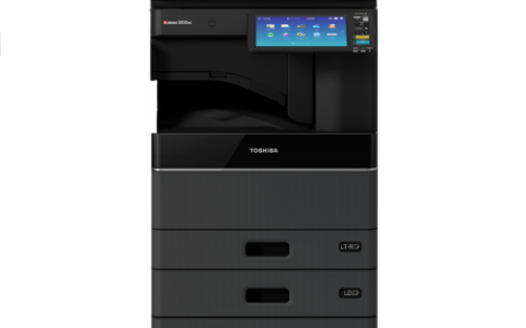
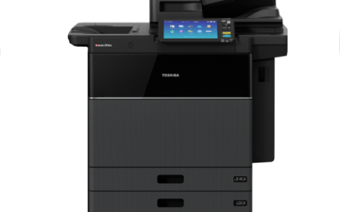
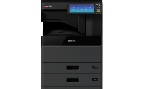
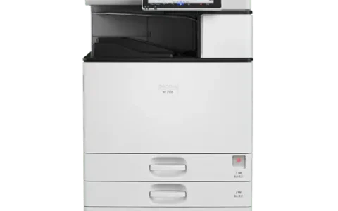
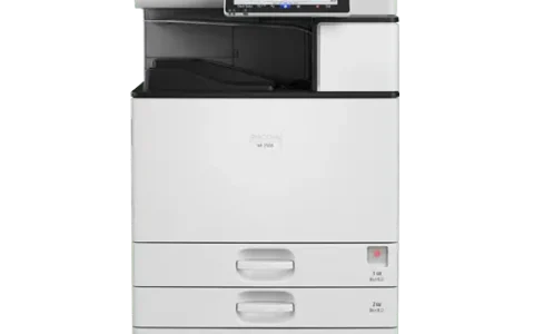
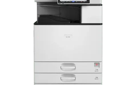
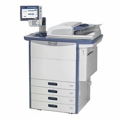
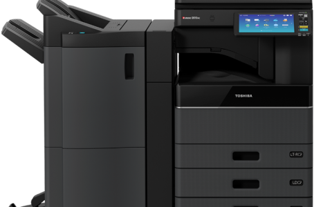
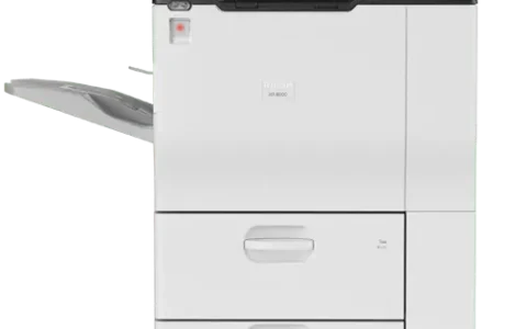
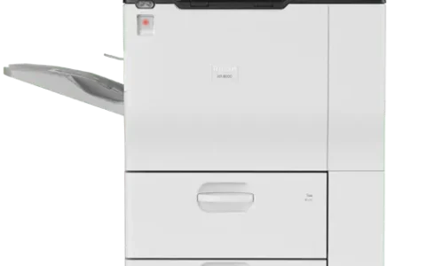
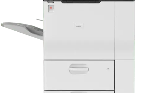
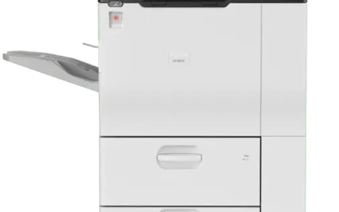
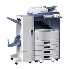
Toshiba e-STUDIO 5508A/6508A/7508A/8508A Service Manual
Toshiba e-STUDIO 5508A / 6508A / 7508A / 8508A Services Manual
Hướng dẫn sử dụng và Mã tự chẩn đoán Toshiba e-STUDIO 5508A / 6508A / 7508A / 8508A;
Sách hướng dẫn này ở định dạng PDF và có Sơ đồ chi tiết, hình ảnh và quy trình đầy đủ để chẩn đoán và sửa chữa Toshiba của bạn.
Bạn có thể in, phóng to hoặc đọc bất kỳ sơ đồ, hình ảnh hoặc trang nào từ sách hướng dẫn này. Mỗi chương trong sách hướng dẫn này đều có đầy đủ chi tiết và bao gồm tất cả các mã mô phỏng, mã sự cố, quy trình bảo trì, quy trình thiết lập lại, quy trình chẩn đoán của máy photocopy Toshiba e-STUDIO. Bạn có thể dễ dàng tìm thấy mọi thứ bạn cần.
Để xem những gì chứa, vui lòng đọc mục lục:

1. FEATURE
1.1 Main Feature of e-STUDIO 5508A/6508A/7508A/8508A
2. SPECIFICATIONS/ACCESSORIES/OPTIONS/SUPPLIES
2.1 Specifications
2.1.1 General
2.1.2 Copy
2.1.3 Print
2.1.4 Scan
2.1.5 e-Filing
2.1.6 Internet Fax
2.1.7 Network Fax (optional)
2.2 Accessories
2.3 System List
2.4 Options
2.5 Supplies
3. OUTLINE OF THE MACHINE
3.1 Sectional View
3.1.1 Front side
3.1.2 Rear side
3.2 Electric Parts Layout
3.3 Symbols and Functions of Various Components
3.3.1 Motors
3.3.2 Fans
3.3.3 Sensors
3.3.4 Switches
3.3.5 Electromagnetic spring clutches
3.3.6 Solenoids
3.3.7 PC boards
3.3.8 Lamps, coils, and heaters
3.3.9 Thermistors and thermostats
3.3.10 Transformer
3.3.11 Others
3.4 Copy Process
3.5 Comparison with e-STUDIO657/857
3.6 General Operation
3.6.1 Overview of Operation
3.6.2 Description of Operation
3.6.3 Detection of Abnormality
3.6.4 Hibernation function
3.7 Control Panel
3.7.1 General Description
3.8 Scanner
3.8.1 General Description
3.8.2 Construction
3.8.3 Functions
3.8.4 Description of Operation
3.8.5 Process of detection of original size
3.9 Laser Optical Unit
3.9.1 General Description
3.9.2 Laser precautions
3.9.3 Slit glass cleaning mechanism
3.10 Paper Feeding System
3.10.1 General Descriptions
3.10.2 Composition
3.10.3 Functions
3.10.4 Description of Operation
3.11 Process Unit Related Section
3.11.1 General description
3.11.2 Composition
3.11.3 Functions
3.11.4 Electric Circuit Description
3.11.5 Functions of the toner cartridge PC board (CTRG)
3.12 Transfer unit
3.12.1 General Descriptions
3.12.2 Composition
3.12.3 Self steering mechanism
3.13 Image Quality Control
3.13.1 General Description
3.14 Fuser Unit
3.14.1 General Description
3.14.2 Composition
3.14.3 Pressure mechanism
3.14.4 Electric Circuit Description
3.15 Exit / Reverse / Duplex Section
3.15.1 General Description
3.15.2 Composition
3.15.3 Description of Operations
3.16 Dual Scan Document Feeder (DSDF)
3.16.1 General Description
3.16.2 DESCRIPTION OF OPERATIONS
3.17 Power Supply Unit
3.17.1 General Description
3.17.2 Composition
3.17.3 Operation of DC Output Circuits
3.17.4 Output Channel
3.17.5 Fuse
4. DISASSEMBLY and REPLACEMENT
4.1 Disassembly and Replacement of Covers
4.1.1 Front lower cover
4.1.2 Front cover
4.1.3 Top right cover
4.1.4 Right top cover
4.1.5 Front right cover (Control panel right cover)
4.1.6 Front top cover (Control panel top cover)
4.1.7 Front lower cover (Control panel lower cover)
4.1.8 Front left cover (Control panel left cover)
4.1.9 Top front cover
4.1.10 Top left cover
4.1.11 Left rear cover
4.1.12 Top rear left cover
4.1.13 Receiving tray
4.1.14 Left middle cover
4.1.15 Left top cover
4.1.16 Left lower cover
4.1.17 Bypass tray unit (Removing tray arm)
4.1.18 Duplexing unit front cover
4.1.19 Duplexing unit rear cover
4.1.20 Paper feed cover
4.1.21 Right rear cover
4.1.22 Rear cover
4.1.23 Top rear cover
4.1.24 Left corner cover
4.1.25 Right corner cover
4.2 Control Panel
4.2.1 Control panel unit
4.2.2 Hinge cover
4.2.3 Signal harness
4.2.4 KEY board/button
4.2.5 DSP board
4.3 Scanner Unit
4.3.1 Original glass
4.3.2 Lens cover
4.3.3 Automatic original detection sensor-1, -2 (S1/S2)
4.3.4 Lens unit/CCD driving PC board (CCD)
4.3.5 Carriage home position sensor (S3)
4.3.6 Exposure lamp (EXP)
4.3.7 Scan motor (M1)
4.3.8 Platen sensor (S4/S5)
4.3.9 Carriage-1
4.3.10 Carriage wire, carriage-2
4.3.11 Scanner damp heater (DH1)
4.3.12 Scanner damp heater thermostat (THMO1)
4.4 Laser Optical Unit
4.4.1 Laser optical unit
4.4.2 Laser optical unit cooling fan (front) (F22)
4.4.3 Laser optical unit cooling fan (rear) (F23)
4.4.4 Shutter
4.4.5 Shutter motor (M38)
4.4.6 Shutter sensor (home position) (S24)
4.4.7 Shutter sensor (end position) (S25)
4.5 Paper Feeding System
4.5.1 Bypass feed tray
4.5.2 Bypass feed unit
4.5.3 Bypass pickup solenoid (SOL8)
4.5.4 Bypass paper sensor (S71)
4.5.5 Bypass pickup roller
4.5.6 Bypass upper unit
4.5.7 Bypass feed roller
4.5.8 Bypass transport roller
4.5.9 Bypass motor (M12)
4.5.10 Bypass separation roller
4.5.11 Bypass feed sensor (S72)
4.5.12 Bypass paper size detection sensor (S70)
4.5.13 Drawer feeding unit
4.5.14 Feed roller
4.5.15 Pickup roller
4.5.16 Separation roller
4.5.17 Transport roller
4.5.18 Drawer detection sensor (S73/S81/S89/S97)
4.5.19 Drawer feed sensor (S78/S86/S94/S102)
4.5.20 Drawer transport sensor (S77/S85/S93/S101)
4.5.21 Drawer empty sensor (S75/S83/S91/S99)
4.5.22 Drawer tray-up sensor (S76/S84/S92/S100)
4.5.23 Drawer bottom sensor (S74/S82/S90/S98)
4.5.24 Registration roller (Rubber)
4.5.25 Registration guide
4.5.26 Registration sensor (S52)
4.5.27 Registration roller (Metal)
4.5.28 2nd transfer side paper clinging detection sensor (S51)
4.5.29 Feed cover sensor (S114)
4.5.30 Drawer
4.5.31 Drawer paper width detection sensor / Drawer paper length
detection sensor (S79/S80/S87/S88/S95/S96/S103/S104)
4.5.32 Registration motor (M39)
4.5.33 Feed/transport drive unit
4.5.34 Transport motor-1 (M40)
4.5.35 Transport motor-2 (M41)
4.5.36 1st/2nd drawer feed motor (M42)
4.5.37 3rd/4th drawer/LCF feed motor (M43)
4.5.38 Paper feed drive unit
4.5.39 3rd drawer transport clutch (CLT4)/3rd drawer feed clutch (CLT5)
4.5.40 4th drawer transport clutch (CLT6)/4th drawer feed clutch (CLT7)
4.5.41 1st/2nd drawer tray-up motor (M44)
4.5.42 3rd/4th drawer/LCF tray-up motor (M45)
4.5.43 Transfer belt paper clinging detection sensor (S47)
4.5.44 T-LCF tray-up motor (M46)
4.5.45 T-LCF end fence motor (M47)
4.5.46 Tandem LCF standby unit
4.5.47 Tandem LCF feeding unit
4.5.48 T-LCF stopper opening/closing solenoid (front) (SOL10)/
T-LCF stopper opening/closing detection sensor (front) (S110)
4.5.49 T-LCF stopper opening/closing solenoid (rear) (SOL11)/
T-LCF stopper opening/closing detection sensor (rear) (S111)
4.5.50 T-LCF bottom sensor (S107)
4.5.51 T-LCF standby side tray paper amount detection sensor (S106)
4.5.52 T-LCF end fence home position sensor (S112)
4.5.53 T-LCF end fence stop position sensor (S113)
4.5.54 T-LCF standby side empty sensor (S109)
4.5.55 T-LCF standby side tray detection sensor (S108)
4.5.56 T-LCF pickup solenoid (SOL9)
4.5.57 1st drawer idling roller
4.6 Process Unit Related Section
4.6.1 Pulling out the process unit (EPU tray)
4.6.2 Drum cleaner unit
4.6.3 Drum
4.6.4 Drum cleaning blade
4.6.5 Blade side seal
4.6.6 Main charger unit
4.6.7 Main charger grid
4.6.8 Needle electrode cleaner
4.6.9 Needle electrode
4.6.10 Discharge LED (ERS-K)
4.6.11 Sub-hopper
4.6.12 Sub-hopper toner sensor (S38)
4.6.13 EPU cover
4.6.14 Sub-hopper toner motor (M19)
4.6.15 Drum surface potential sensors control PC board (V0S board)
(V0S) (85ppm only)
4.6.16 Auger lock detection sensor (S42)
4.6.17 Mixing ozone fan (F17)
4.6.18 Needle electrode cleaner detection sensor (S30)
4.6.19 Needle electrode cleaner motor (M23)
4.6.20 V0 sensor shutter solenoid (SOL) (e-STUDIO8508A only)
4.6.21 Drum surface potential sensor (S34) (e-STUDIO8508A only)
4.6.22 Drum thermistor (THM1)
4.6.23 Developer unit
4.6.24 Developer material
4.6.25 Developer sleeve
4.6.26 Auto-toner sensor (S26)
4.6.27 Drum and developer drive unit
4.6.28 Drum motor (M27)
4.6.29 Developer unit motor (M29)
4.6.30 Developer unit mixer motor (M30)
4.6.31 Waste toner box
4.6.32 Waste toner amount detection sensor (S13)
4.6.33 Waste toner box full detection sensor (S14)
4.6.34 Waste toner box detection sensor (S16)
4.6.35 Ozone filter-1
4.6.36 Ozone filter-2
4.6.37 Power supply unit cooling fan (F37)
4.6.38 Ozone filter 3
4.6.39 Toner filter
4.6.40 Toner motor (M15)
4.6.41 Toner cartridge paddle rotation detection sensor (S8)
4.6.42 Waste toner transport motor (M33)
4.6.43 Waste toner transport unit
4.6.44 Ozone suctioning fan (F24)
4.6.45 Fuser insulation fan (F21)
4.6.46 Temperature/humidity sensor (S12)
4.6.47 Toner motor interlock switch (SW3)
4.6.48 EPU cooling fan (F14)
4.6.49 Scattered toner suctioning fan (F25)
4.6.50 Main power switch (SW1)
4.7 Transfer Unit
4.7.1 Pulling out the transfer belt unit
4.7.2 2nd transfer facing roller cleaning pad
4.7.3 Transfer belt cleaning unit
4.7.4 Transfer belt cleaning blade
4.7.5 Transfer belt cleaner side seal
4.7.6 Transfer belt unit (TBU)
4.7.7 Transfer belt
4.7.8 1st transfer roller
4.7.9 Cleanable facing roller
4.7.10 Tension roller
4.7.11 2nd transfer facing roller
4.7.12 2nd transfer unit (TRU)
4.7.13 2nd transfer roller
4.7.14 Transfer belt motor (M13)
4.7.15 Transfer belt motor unit
4.8 Image Quality Control
4.8.1 Image quality control unit
4.8.2 Image position aligning sensor (center) (S21)
4.8.3 Image quality shutter solenoid (SOL3)
4.9 Fuser Unit
4.9.1 Fuser unit
4.9.2 Pressure roller cover
4.9.3 Fuser unit transport guide
4.9.4 Entrance guide cover
4.9.5 Separation guide
4.9.6 Separation plate
4.9.7 Fuser belt
4.9.8 Fuser belt lubricating sheet / Fuser belt pad
4.9.9 Fuser belt center thermistor (THM5) / edge thermistor (THM6) /
thermostat (THMO4)
4.9.10 Pressure roller
4.9.11 Fuser belt rotation detection sensor (S49)
4.9.12 Pressure roller contact/release sensor (S48)
4.9.13 IH coil (IH-COIL)
4.9.14 Fuser motor (M6)
4.9.15 Presure rollor contact/release motor (M48)
4.9.16 IH board cooling fan (exhaust) (F8)
4.9.17 IH board cooling fan (suction) (F9)
4.9.18 Fuser unit jam releasing LED (LED)
4.9.19 Filter cover
4.10 Exit / Reverse / Duplex Section
4.10.1 Upper exit section cooling fan (rear) (F32) /
Upper exit section cooling fan (front) (F33)
4.10.2 Lower exit section cooling fan (rear) (F34) /
Lower exit section cooling fan (front) (F35)
4.10.3 Lower exit section cooling fan (under) (F36)
4.10.4 Exit motor (M2)
4.10.5 Upper paper exit sensor (S61) / Upper exit tray paper full
detection sensor (S62)
4.10.6 Lower paper exit sensor (S63)
4.10.7 Reverse section stationary jam detection sensor (S60)
4.10.8 Reverse path cover switch (SW5)
4.10.9 Upper paper exit roller
4.10.10 Lower paper exit roller
4.10.11 Bridge unit
4.10.12 Bridge unit front cover
4.10.13 Bridge unit lower cover
4.10.14 Bridge unit transport entrance motor (M4) / Reverse motor (M3)
4.10.15 Bridge unit transport exit motor (M5)
4.10.16 Bridge unit upper cover
4.10.17 Bridge unit transport roller-1
4.10.18 Bridge unit transport roller-2
4.10.19 Bridge unit transport roller-3
4.10.20 Reverse roller
4.10.21 Bridge unit exit roller-1
4.10.22 Bridge unit exit roller-2
4.10.23 Transport path switching solenoid (bridge unit/reverse section) (SOL1)
4.10.24 Transport path switching solenoid (bridge unit/reverse section) (SOL2)
4.10.25 Bridge unit path entrance sensor (S55)
4.10.26 Bridge unit path exit sensor (S56)
4.10.27 Reverse sensor (S59)
4.10.28 Reverse section stationary jam detection sensor (S58)
4.10.29 Bridge unit cooling fan (F6)
4.10.30 Front cover opening/closing detection switch (SW9) /
Bridge unit connecting detection switch (SW8)
4.10.31 Duplexing bridge unit
4.10.32 Duplexing unit opening/closing detection sensor (S64)
4.10.33 Reverse path sensor (S57)
4.10.34 Duplexing bridge unit transport roller
4.10.35 Duplexing unit upper cover
4.10.36 Duplexing unit front side cover
4.10.37 Duplexing unit rear side cover
4.10.38 Reversed paper cooling fan (F11)
4.10.39 ADU transport motor (M7)
4.10.40 ADU feed motor (M8)
4.10.41 ADU board (ADU)
4.10.42 ADU transport roller-1
4.10.43 ADU transport roller-2
4.10.44 ADU transport roller-3
4.10.45 Duplexing unit path exit sensor (S67)
4.10.46 Fuser transport sensor (S65)
4.10.47 Duplexing unit path entrance sensor (S66)
4.10.48 Duplexing unit interlock switch / Duplexing unit cover opening/
closing detection switch (SW7)
4.10.49 IH interlock switch (SW4)
4.10.50 Interlock switch (SW2)
4.10.51 Fuser unit exhaust heat fan / Bridge unit exhaust heat fan (F1/F2)
4.11 Dual Scan Document Feeder (DSDF)
4.11.1 Removing the DSDF
4.11.2 Installing the DSDF
4.11.3 DSDF pickup unit
4.11.4 DSDF separation roller
4.11.5 DSDF pickup roller
4.11.6 DSDF feed roller
4.11.7 DSDF rear cover
4.11.8 DSDF front cover
4.11.9 Original jam access cover
4.11.10 DSDF left cover
4.11.11 DSDF-LED PC board (LEDD)
4.11.12 DSDF control PC board (DLGD)
4.11.13 Original tray
4.11.14 DSDF tray original length sensor-1 (SD1) /
DSDF tray original length sensor-2 (SD2)
4.11.15 DSDF tray original width sensor (SD3)
4.11.16 DSDF original empty sensor (SD4)
4.11.17 DSDF feed sensor (SD5) / DSDF tray lift upper limit sensor (SD9)
4.11.18 DSDF original width detection sensor-1 (SD7) /
DSDF original width detection sensor-2 (SD8)
4.11.19 DSDF registration sensor (SD6)
4.11.20 DSDF cooling fan motor (FD1)
4.11.21 DSDF upper cover interlock switch (SWD2)
4.11.22 DSDF registration motor (MD3)
4.11.23 DSDF read motor (MD4)
4.11.24 DSDF exit motor (MD5)
4.11.25 DSDF lower cover interlock switch (SWD1)
4.11.26 DSDF feed motor (MD1)
4.11.27 DSDF separation motor (MD2)
4.11.28 Intermediate transport unit
4.11.29 DSDF read-in sensor-1 (SD11) / DSDF read-in sensor-2 (SD12)
4.11.30 DSDF exit sensor (SD13) / DSDF tray lift lower limit sensor (SD10)
4.11.31 Lower transport unit
4.11.32 DSDF shading sheet HP sensor (SD14) /
DSDF lower cover opening/closing detection sensor (SD15)
4.11.33 DSDF-CCD module (CCDD)
4.12 Removal and Installation of Options
4.12.1 Large Capacity Feeder (LCF)
4.12.2 Finisher
4.12.3 Hole Punch Unit
5. SELF-DIAGNOSTIC MODE
5.1 Overview
5.2 Description Rule for Each Menu and Mode
5.3 Service UI
5.3.1 Overview
5.3.2 Operation procedure
5.3.3 Starting the FS Menu from the normal mode
5.4 03 TEST MODE
5.4.1 Output check
5.4.2 Input check
5.5 04 TEST PRINT MODE
5.6 05 ADJUSTMENT MODE
5.6.1 Adjustment
5.6.2 TEST PRINT
5.7 08 SETTING MODE
5.8 20 PM SUPPORT MODE
5.9 30 LIST PRINT MODE
5.9.1 Operation procedure
5.9.2 List Printing
5.10 FAX
5.10.1 11 FAX CLEAR MODE
5.10.2 12 FAX LIST PRINT MODE
5.10.3 13 FAX FUNCTION MODE
5.10.4 19 RAM EDIT MODE
5.11 01 Control Panel Check Mode
5.11.1 Screen transition
5.11.2 Checking of the LCD back light and LEDs
5.11.3 Checking of the LCD display, hard keys and digital keys
5.11.4 Checking of the LCD touch sensor and USB storage device connection
5.12 73 Firmware Assist Mode
5.12.1 Overview
5.12.2 Operation procedure
5.12.3 Functions
5.13 74 HDD Assist Mode
5.13.1 Overview
5.13.2 Operation procedure
5.13.3 Functions
5.14 75 File System Recovery Mode
5.14.1 Overview
5.14.2 Operation procedure
5.14.3 Functions
5.15 76 SRAM Maintenance Mode
5.15.1 Overview
5.15.2 Operation procedure
5.15.3 Functions
5.16 Pixel Counter
5.16.1 Outline
5.17 Batch Setting for Self-Diagnostic Codes
5.17.1 General description
5.17.2 Applicable codes
5.17.3 Setting files
5.17.4 Result files
5.17.5 Operation procedure
6. SETTING / ADJUSTMENT
6.1 Image Related Adjustment
6.1.1 Adjustment Order
6.1.2 Adjustment of Auto-Toner Sensor
6.1.3 Performing Image Quality Control
6.1.4 Image Dimensional Adjustment
6.1.5 Paper alignment at the registration roller
6.1.6 Image dimensional adjustment at the printing section
6.1.7 Scanner related adjustment
6.2 Image Quality Adjustment (Copying Function)
6.2.1 Automatic gamma adjustment (600dpi)
6.2.2 Density adjustment
6.2.3 Gamma balance adjustment
6.2.4 Background adjustment
6.2.5 Sharpness adjustment
6.2.6 Setting range correction
6.2.7 Adjustment of smudged text in black
6.2.8 Emission level adjustment
6.2.9 Judgment threshold adjustment for blank originals
(common for copy and fax)
6.2.10 Background offsetting adjustment for DSDF
(common for copy, scan and fax)
6.2.11 Background offsetting adjustment in back side for DSDF
(common for copy, scan and fax)
6.2.12 RADF scan noise reduction
6.3 Image Quality Adjustment (Printing Function)
6.3.1 Automatic gamma adjustment
6.3.2 Gamma balance adjustment
6.3.3 Upper limit value in the Toner Saving Mode (1200dpi)
6.3.4 Thin line width lower limit adjustment
6.3.5 Emission level adjustment
6.3.6 Density adjustment of graphic lines (1200dpi)
6.3.7 Gradation switching for black mode printing text
6.3.8 Adjustment of smudged text in black
6.4 Image Quality Adjustment (Scanning Function)
6.4.1 Gamma balance adjustment
6.4.2 RGB Color balance adjustment
6.4.3 Density adjustment
6.4.4 Background adjustment (Color)
6.4.5 Background adjustment (Black/Grayscale)
6.4.6 Judgment threshold for ACS
6.4.7 Sharpness adjustment
6.4.8 Contrast adjustment
6.4.9 Fine adjustment of black density
6.4.10 RGB conversion method selection
6.4.11 Adjustment of saturation
6.4.12 Background offsetting adjustment for DSDF
(common for copy, scan and fax)
6.4.13 Background offsetting adjustment in back side for DSDF
(common for copy, scan and fax)
6.4.14 Adjustment of the capacity and image quality of SlimPDF
6.4.15 Surrounding void amount adjustment
6.4.16 Judgment threshold adjustment for blank originals
(common for copy and fax)
6.4.17 JPEG compression level adjustment
6.4.18 Color conversion table selection
6.4.19 DSDF scan noise reduction
6.5 Image Quality Adjustment (FAX Function)
6.5.1 Density adjustment
6.5.2 Emission level adjustment
6.5.3 Background offsetting adjustment for DSDF
(common for copy, scan and fax)
6.5.4 Background offsetting adjustment in back side for DSDF
(common for copy, scan and fax)
6.6 Scanner
6.6.1 Adjustment carriages-1 positions
6.6.2 Position adjustment of CCD lens unit
6.6.3 Belt tension adjustment of the Scan motor
6.7 Paper Feeding System
6.7.1 Separation roller pressure force adjustment
6.7.2 Sheet sideways deviation caused by paper transporting adjustment
6.7.3 Adjusting the clearance of the paper and side guides
6.8 Process Unit Related Section
6.8.1 High-Voltage Transformer Setting
6.8.2 Adjustment of the Auto-Toner Sensor
6.8.3 Adjustment of the doctor-sleeve gap
6.9 Transfer Unit
6.9.1 Adjustment of the degree of the transfer belt unit parallelization
6.10 Image Quality Control
6.10.1 Performing Image Quality Control
6.11 Fuser Unit
6.11.1 Adjustment of the Separation Guide Gap
6.12 Adjustment of the Dual Scan Document Feeder (DSDF)
6.12.1 Adjustment of Position
6.12.2 Adjustment of Height
6.12.3 Adjustment of Skew
6.12.4 Adjustment of the Leading Edge Position
6.12.5 Adjustment of Horizontal Position
6.12.6 Adjustment of Copy Ratio
6.12.7 DSDF read-in sensor-1 adjustment
6.12.8 Platen Sheet
6.13 Adjustment of the Finisher (MJ-1111/1112)
6.13.1 Adjusting the Alignment Position
6.13.2 Adjusting the Stapling Position
6.13.3 Stapling/folding position adjustment in saddle stitch unit (MJ-1112)
6.13.4 Folding position adjustment
6.13.5 Stapling position adjustment
6.13.6 Saddle Stitch Skew Adjustment (MJ-1112)
6.14 Adjustment of Hole punch unit (MJ-6106)
6.14.1 Stopping Position Adjustment
7. PREVENTIVE MAINTENANCE (PM)
7.1 General Description
7.2 PM Display
7.2.1 General Description
7.2.2 PM Display Conditions
7.2.3 PM Display Contents
7.2.4 Counter Clearing
7.3 General Descriptions for PM Procedure
7.4 PM Support Mode
7.4.1 General Description
7.4.2 Operational flow
7.4.3 Operational screen
7.4.4 Access tree
7.5 General Description
7.6 Preventive Maintenance Checklist
7.6.1 Scanner
7.6.2 Feed unit
7.6.3 Duplexing unit
7.6.4 Bypass feed unit
7.6.5 Main charger
7.6.6 Drum / Cleaner unit / Filter
7.6.7 Developer unit
7.6.8 Waste toner box
7.6.9 Transfer belt unit / Transfer belt cleaning unit
7.6.10 Image quality control unit
7.6.11 2nd transfer roller unit
7.6.12 Fuser unit
7.6.13 Bridge unit
7.6.14 Paper exit unit
7.6.15 DSDF
7.6.16 LCF (MP-2502)
7.6.17 Finisher (MJ-1111/1112)
7.6.18 Hole punch unit (MJ-6106)
7.7 Storage of Supplies and Replacement Parts
7.8 PM KIT
7.9 Maintenance Part List
7.9.1 How to attach the DSDF stopper jig
7.10 Grease List
7.11 Machine Refreshing Checklist
8. ERROR CODE and TROUBLESHOOTING
8.1 General Descriptions
8.1.1 If a problem continues even after performing all troubleshooting
8.1.2 Collection of debug logs with a USB device
8.1.3 Traceability label
8.2 Error Code List
8.2.1 Jam
8.2.2 Service call
8.2.3 Error in Internet FAX / Scanning Function
8.2.4 Printer function error
8.2.5 TopAccess related error/Communication error with external application
8.2.6 MFP access error
8.2.7 Maintenance error
8.2.8 Network error
8.2.9 Notification
8.2.10 Error history
8.3 Diagnosis and Prescription for Each Error Code
8.3.1 Check item
8.3.2 Paper transport jam (paper exit section)
8.3.3 Paper misfeeding
8.3.4 Paper transport jam
8.3.5 Other paper jam
8.3.6 Cover open jam
8.3.7 DSDF jam
8.3.8 Jam in bridge unit
8.3.9 Paper jam in finisher section
8.3.10 Paper jam in saddle stitcher section
8.3.11 Paper jam in puncher unit
8.3.12 Other paper jam
8.3.13 Paper feeding system related service call
8.3.14 Scanning system related service call
8.3.15 Fuser unit related service call
8.3.16 Communication related service call
8.3.17 DSDF related service call
8.3.18 Circuit related service call
8.3.19 Laser optical unit related service call
8.3.20 Finisher related service call
8.3.21 Image control related service call
8.3.22 Copy process related service call
8.3.23 Other service call
8.3.24 Error in Internet FAX / Scanning Function
8.3.25 Printer function error
8.3.26 TopAccess related error/Communication error with external application
8.3.27 MFP access error
8.3.28 Maintenance error
8.3.29 Network error
8.4 Other errors
8.4.1 Drum surface potential sensor control related troubleshooting
(only for 85ppm)
8.4.2 Troubleshooting at unpacking
8.4.3 Drum surface potential sensor control related troubleshooting
when setting up the equipment at unpacking (85ppm only)
8.4.4 Equipment operation disabled after the installation of option(s)
8.4.5 Wireless LAN connection disabled
8.4.6 When the duplexing unit cover open display cannot be released
8.4.7 Troubleshooting for one-time dongle
8.4.8 Countermeasure for stain on paper back side
8.4.9 Measures against exit paper side deviation
8.4.10 Error code “M00” is displayed while updating firmware
8.4.11 Problems in paper exiting
8.4.12 Countermeasure for stains (stripe-shaped) on the back side of
the paper occurring immediately after the drum cleaner unit is
removed and then reinstalled
8.5 Troubleshooting for the Image
8.5.1 Uneven pitch and jitter image
8.5.2 Black spot
8.5.3 Abnormality of image density / Gray balance
8.5.4 Background fogging
8.5.5 Moire/lack of sharpness
8.5.6 Toner offset
8.5.7 Blurred image
8.5.8 Poor fusing
8.5.9 Blank print
8.5.10 Solid print
8.5.11 White banding or white void (in feeding direction)
8.5.12 White banding (at right angles to feeding direction)
8.5.13 Skew (slantwise copying)
8.5.14 Black banding (in feeding direction)
8.5.15 Black banding (at right angles to feeding direction)
8.5.16 White spots
8.5.17 Poor transfer
8.5.18 Uneven image density 1
8.5.19 Uneven image density 2
8.5.20 Faded image (low density)
8.5.21 Image dislocation in feeding direction
8.5.22 Image jittering
8.5.23 Poor cleaning
8.5.24 Uneven light distribution
8.5.25 Blotched image
8.5.26 Stain on the paper back side
8.5.27 White void in the halftone
8.5.28 Paper wrinkle
8.5.29 Residual image
8.5.30 Feathered image
8.5.31 Low density image (rear side)
8.5.32 Image tilting on leading edge
9. REPLACEMENT OF PC BOARDS/HDD
9.1 Removal and Installation of PC Boards/HDD
9.1.1 SYS board cover
9.1.2 SYS board (SYS)
9.1.3 SRAM
9.1.4 Main memory (DIMM)
9.1.5 SYS board case
9.1.6 SYS board cooling fan (F27)
9.1.7 LGC board (LGC)
9.1.8 EEPROM
9.1.9 LGC/PFC board case
9.1.10 PFC board (PFC)
9.1.11 Hard disk (HDD)
9.1.12 Switching regulator (PS)
9.1.13 Switching regulator case
9.1.14 High-voltage transformer (HVT)
9.1.15 FIL-AC board
9.1.16 DAMP board (Destinations other than NAD/NAC/MJD/MJC)
9.1.17 DSDF-I/F board
9.1.18 IH board
9.1.19 DRV board
9.1.20 CTIF board
9.2 Precautions, Procedures and Settings for Replacing PC Boards and HDD
9.2.1 Precautions when replacing PC boards
9.2.2 HDD fault diagnosis
9.2.3 Precautions and procedures when replacing the HDD
9.2.4 Precautions and procedures when replacing the SYS board
9.2.5 Precautions and procedure when replacing the SRAM
9.2.6 Procedures when replacing the LGC board
9.2.7 Procedures and settings when replacing EEPROM (for LGC board)
9.2.8 Procedures and settings when replacing the Lens unit
9.2.9 Firmware confirmation after the PC board/HDD replacement
9.2.10 License re-registration using the one-time dongle
9.3 Precautions for Installation of GP-1070 and Disposal of HDD/Board
9.3.1 Precautions for Installation of GP-1070
9.3.2 Precautions when disposing of HDD
9.3.3 Precautions when disposing of the SYS board
9.3.4 Precautions when disposing of the SRAM
10. REMOTE SERVICE
10.1 Auto Supply Order
10.1.1 Outline
10.1.2 Setting Item
10.1.3 Setting procedure
10.1.4 Order Sheet Format
10.2 Service Notification
10.2.1 Outline
10.2.2 Setting
10.2.3 Items to be notified
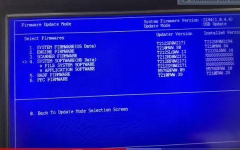
11. FIRMWARE UPDATING
11.1 Overview
11.2 Firmware Updating with USB Device
11.2.1 Updating methods
11.2.2 Firmware type and data file name for updating
11.2.3 Folder configuration of a USB device
11.2.4 Update procedure
11.3 Confirmation of the updated data
12. BACKUP FUNCTION
12.1 Data Cloning
12.1.1 General description
12.1.2 Precautions
12.1.3 Backup files
12.1.4 Cloning procedure
12.2 AES Data Encryption Function Setting
12.2.1 General description
12.2.2 Precautions
12.2.3 Setting procedure
12.2.4 Procedure for disabling data encryption function
12.2.5 Procedure for discarding HDD when data encryption function is enabled
12.3 High Security Mode
12.3.1 General description
12.3.2 Prior confirmation
12.3.3 Procedure for entering the High Security Mode
12.3.4 Precautions
13. EXTERNAL COUNTERS
13.1 Outline
13.2 Signal
13.2.1 Pin Layout
13.2.2 Details of the signals
13.3 Notices
13.3.1 Setting code
13.3.2 Setting value change and restrictions when using the Card Controller
13.3.3 Setting value change and restrictions when using the coin controller
13.3.4 Installation of External Counter
13.3.5 Setting value
13.3.6 Restrictions when using the external counter
14. WIRE HARNESS CONNECTION
14.1 AC Wire Harness
14.2 DC Wire Harness / Electric Parts Layout
14.2.1 DC Wire Harness
14.2.2 Electric Parts Layout
14.2.3 DSDF Harness Diagram
Công ty PHÚ NGỌC KHANG Chuyên cung cấp tất cả các dòng máy photocopy hãng toshiba, Ricoh. Và có bán Tài liệu hướng dẫn sửa chữa máy photocopy ( Service manual ) tất cả các dòng. Liện Hệ 0948 364 132
Mọi chi tiết vui lòng liên hệ:
Công ty TNHH PHÚ NGỌC KHANG
Địa chỉ: Số 97A/4, Tổ 2, Khu Phố 12, Thành phố Biên Hoà, Đồng Nai
Điện thoại: 0948 364 132
Email: info@phungockhang.com
Website:Phungockhang.com

